Table of Contents
- Getting Started
- Resistors
Tube Sockets
- Semiconductors
- Capacitors
- Final Assembly
- Checkout
- Setting the Bias
- Enclosures
Tube Sockets
Next you will be installing the tube sockets. It is absolutely imperative that you be sure that they are oriented correctly before soldering. It is almost impossible to remove a tube socket without damaging the board or the socket.
The sockets are installed from the top of the board and soldered from the bottom. Care must be exercised to avoid applying too much solder, since it will flow down the pins on the socket and into the socket itself. In extreme cases solder will actually fill up the socket, making it impossible to insert a tube. Check your first few pins from the top before soldering them all. If you don't use enough solder the joint may fracture when you are changing tubes.
A common old trick is to insert an old tube into the socket before soldering. This is usually done to insure pin alignment. I don't recommend this because it is too easy to solder the tube into the socket. The 8, 4 and many 9 pin tubes are made with solder on the pins. Too much heat, it will melt, and the tube is permanently soldered into the socket. I have done this and there is no way to get it out!
Octal (4 pin)
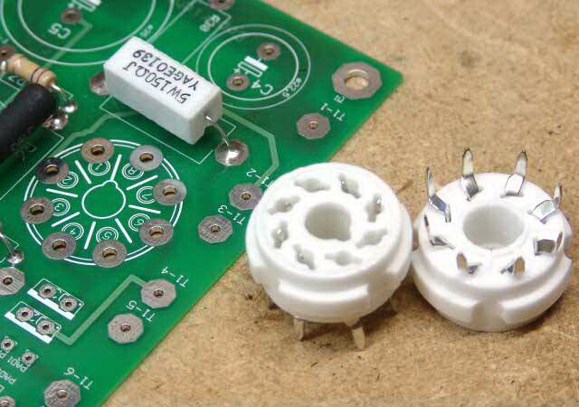 First you will install the octal socket for V-1. There is only one of these, but I already had this picture, so I used it. Note that the board is clearly marked as to the orientation of this socket, however the socket will fit into the board in any orientation.
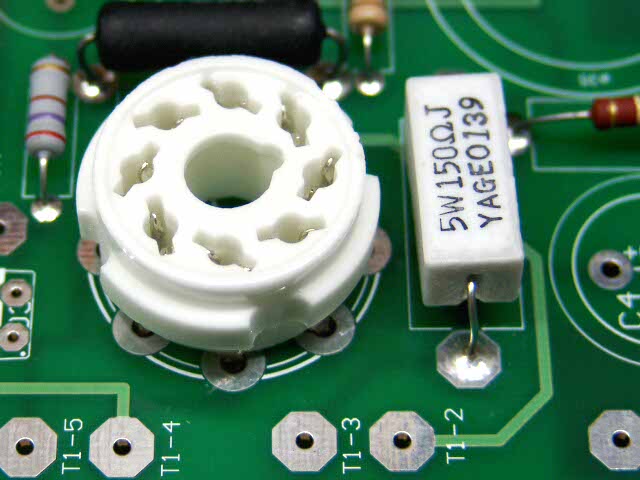 Insuring that the guide pin notch on the socket lines up with the silkscreen printed on the board, insert the socket into the board. Some manipulation of the individual pins may be needed.
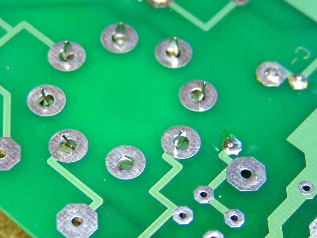 While holding the socket and the board, carefully flip the assembly over onto the work area. Place a small object under the other end of the board so that the board is level and the socket sits flush against the board. I don't recommend bending the pins to hold the socket in. This makes it almost impossible to remove the socket if it ever needs replacement.
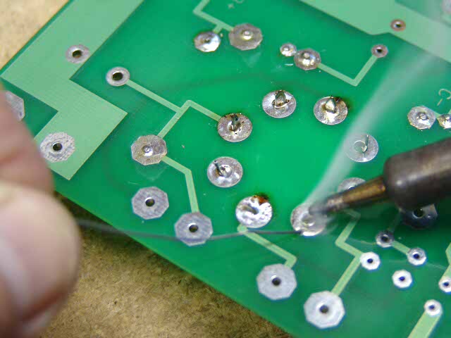 Carefully solder the socket in place, one pin at a time. If you have never done this before, flip the board over after soldering each pin and make sure that excess solder did not run down the pin into the socket. This is unlikely with the octal socket, but it is good to check.
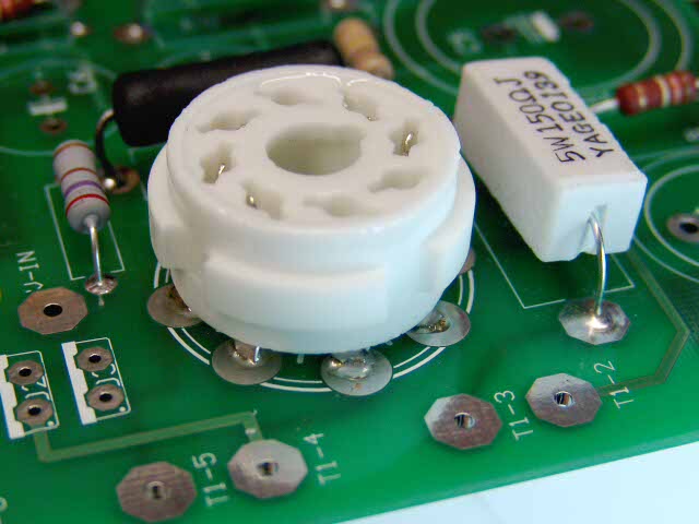 The soldered socket should look like this.
Noval (9 pin)
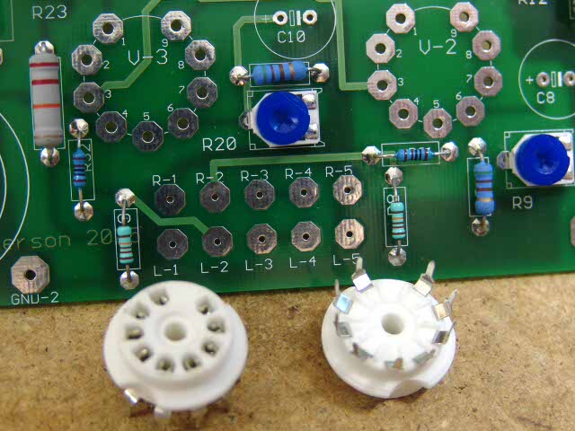 Next you will install the two 9 pin sockets V-2 and V-3. These sockets come in several styles and colors. Yours may be different, but they all install in the same manner.
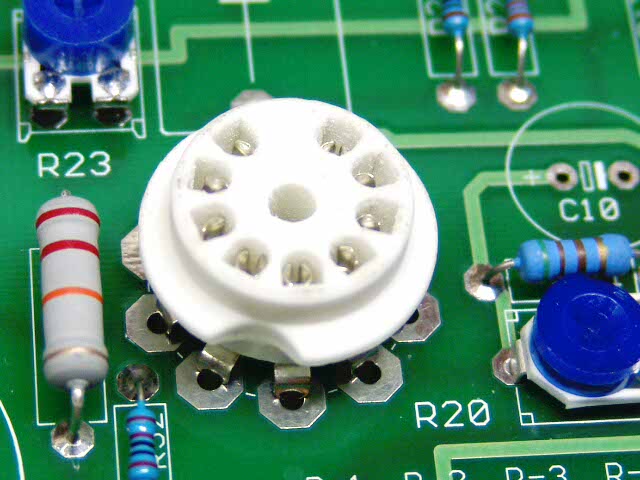 Insert one of the sockets into the board. Some manipulation of the individual pins may be needed. These will only fit into the board one way.
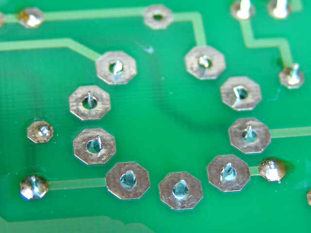 The bottom of the board should look like this before soldering. The socket is resting on the books to keep it flush with the board.
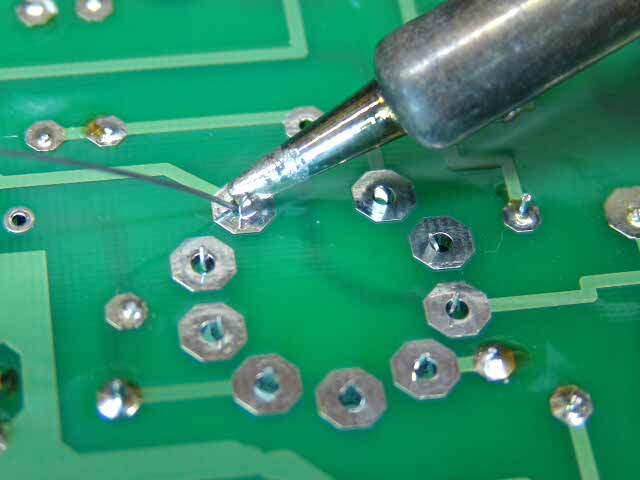 If the socket is flush to the board, and straight, solder it in place. Check each pin for excess solder on the top side of the board.
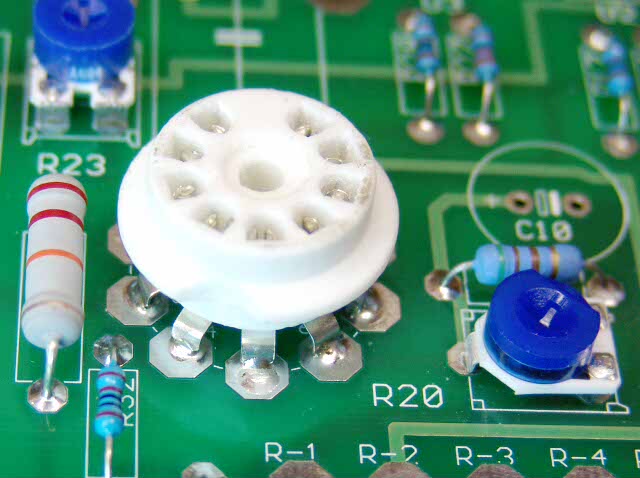 The completed socket should look like this.
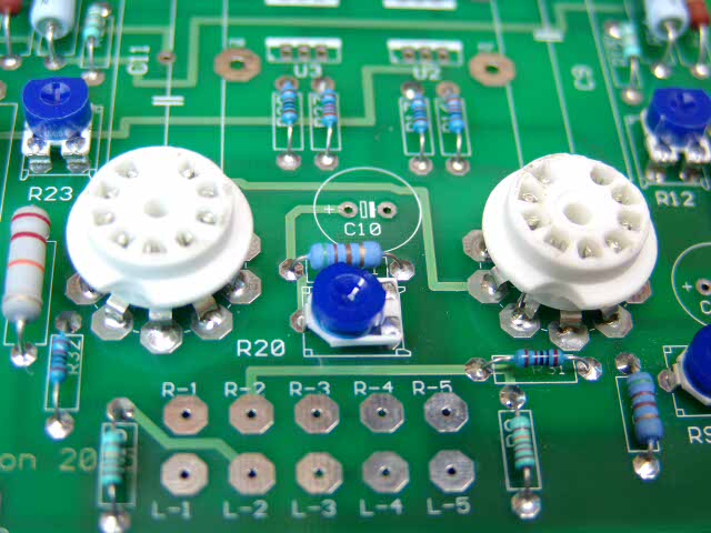 Insert and solder the other 9 pin socket. They should look like these. Your sockets may be slightly different, but they all install the same.
4 Pin
At this point you are going to install the 4 pin sockets for the output tubes. Since there are no sockets available for 4 pin tubes, that were designed for PC board mounting, conventional chassis mount sockets must be used. This makes the installation of these sockets a bit unconventional. Look at all of the photos, and read this entire section before proceeding.
The 4 pin sockets come in two types, with or without a mounting flange. Either type will work here. I purchased some NOS (new OLD stock) ceramic sockets from one of the tube oriented catalogs. I had nothing but trouble with these. Since they were at least 50 years old the tin coating on the pins had oxidized and become brittle. They were intermittent, and one broke when I changed a tube. I don't recommend these. There are also 4 pin sockets that were designed for chassis mounting. These are much larger than the ones shown below, and are not suitable for use in this board.
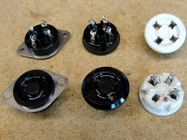
The black sockets are "New production Amphenol" they have worked well for me in 8 amplifiers. Either type works in this amp. The flanged ones are good for mounting a cover plate. The white ones are NOS ceramic sockets. Yes the one on the bottom actually came with one pin missing. I tried them in one amp, and I had to remove them due to poor quality.
IMPORTANT! The numbers that are silk-screened on the board for the pin numbers is INCORRECT. Please ignore it and install the 4 pin sockets as shown below. The numbering is missing on one of the 4 pin tubes, and incorrect on the other one. This will be fixed on the next batch of boards.
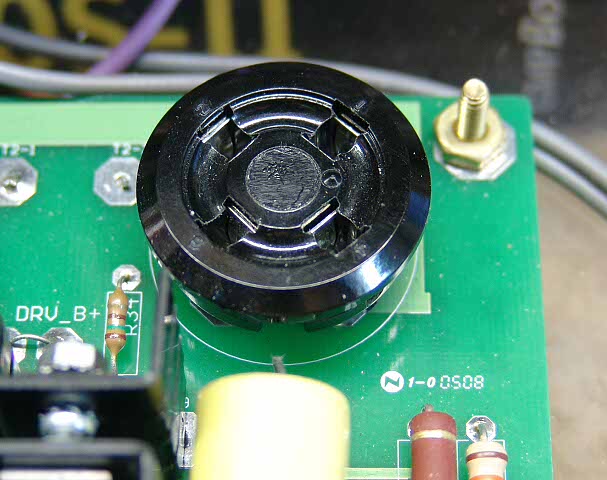
Look at this picture of a completed board. You will see that there are numbers on the socket next to the pins. There is a dot on the socket between pins 1 and 4. The number 1 and number 4 pins are slightly larger than the other two. Look at the pictures below also. Examine your sockets and determine which pins are number 1 and number 4. Not all sockets have all of these features. Some have the pin numbers on the bottom. If you are looking at the board from the top, held such that the printing is correctly oriented, pins 1 and 4 (the larger diameter pins) are to the right. This is very important, once the socket is installed it can't be removed without destroying it.
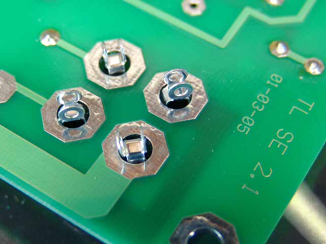 When you are sure of the orientation push the socket through the board until the solder lugs come through. Do not attempt to push it any further.
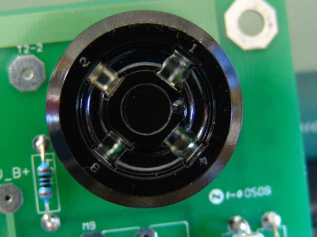 This is a picture of the socket after it is inserted into the board. Here the dot and the pin numbers are clearly visible. If you look carefully you can see the size difference between the pins on the left, and the pins on the right. After your socket is inserted it should look like this. Make sure before bending.
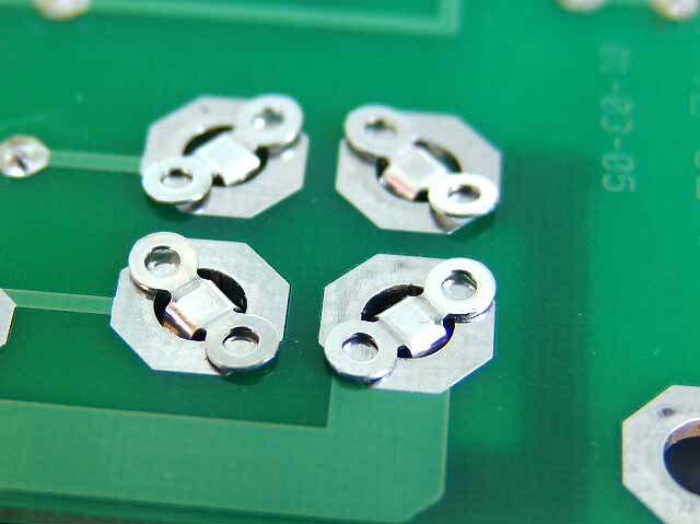 When you are sure that the socket is correctly oriented bend the solder lugs on each pin over as shown. They should be reasonably flat, but don't try to make them perfect. If you bend them too much they will break off. If you break one tab off the socket is probably OK. I have a broken tab on the 845SE board, and it has not given me any problems.
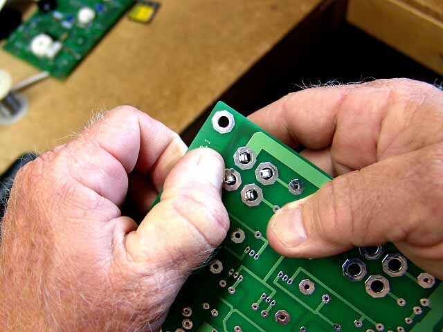
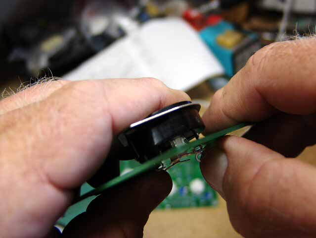 I hold the board and socket in one hand, and bend the pins with my other hand. I will push the tab over in one single motion and not try to re-bend it. I can do this with my finger nail, but you may want to use a small screwdriver, or other tool. All of the pressure is on the socket itself don't exert much force on the board.
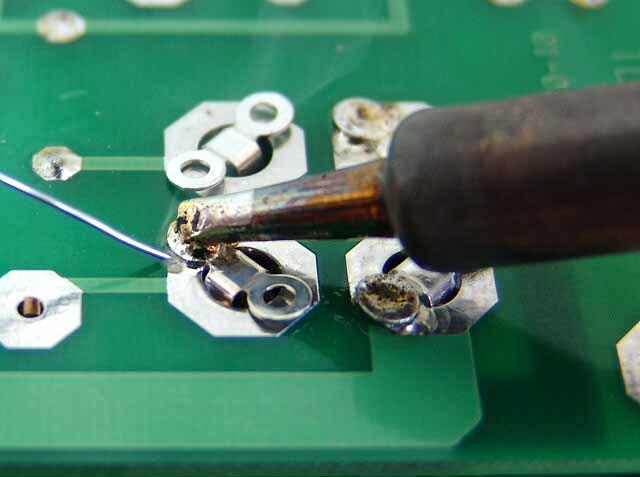 After the tabs are bent over, solder each one to the board, as shown. The board should be positioned such that the socket is not touching anything, it should be hanging over the edge of a book so that the socket hangs by its own weight and the tabs are nearly flush with the board. Use enough solder to securely solder each tab to the board, but not enough to flow through the board to the other side. Do not try to fill the entire hole in the board. Treat this like 8 separate solder connections, not 4. I will put the tip in the hole in the tab and flow the solder from underneath the edge of the tab as shown in the photo.
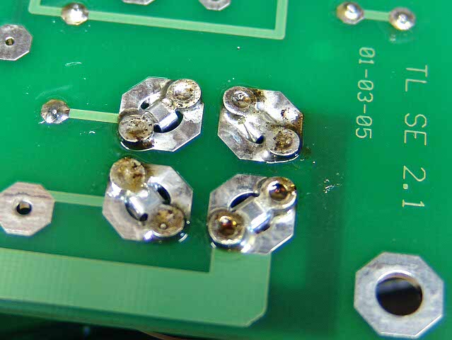 Here is a picture of a completed socket.
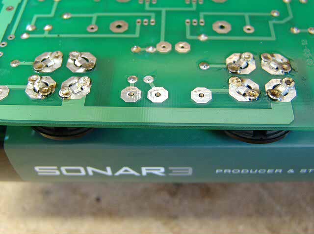 Install and solder the second 4 pin socket in the same manner as the first.
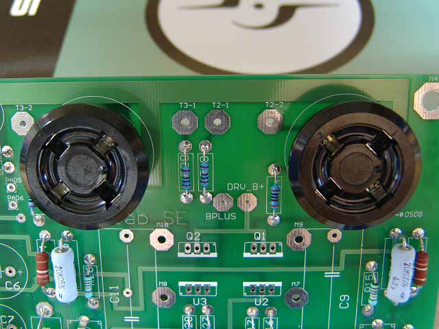 Top view of both sockets.
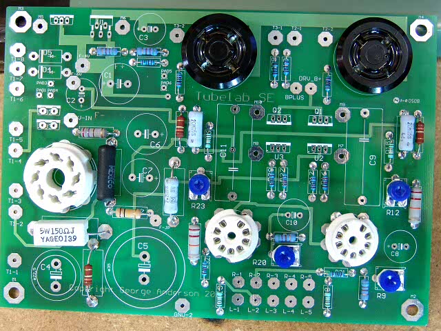 Your board should look like this at this point. If it does proceed to the semiconductors page.