Table of Contents
- Getting Started
Resistors
- Tube Sockets
- Semiconductors
- Capacitors
- Final Assembly
- Checkout
- Setting the Bias
- Enclosures
Resistors
The resistors are installed first on the board. Many of them are the smallest components used in this design and the can be difficult to install once the larger components have been installed. They are also the easiest to install, since they are relatively immune to damage from excessive soldering heat. I recommend installing the resistors in numerical order beginning with R1 and ending with R35. Some builders prefer to install all of the like valued resistors at the same time, going out of sequence. I find that this increases the probability of error, and doesn't save much time. I also recommend printing out the check list, and checking off each part as it is installed. Resistors have no polarity and may be installed in either direction. Some builders will take the time to face all the resistors in the same direction. I do not have the patience for that, but it is perfectly acceptable. Pictures are provided for many of the steps.
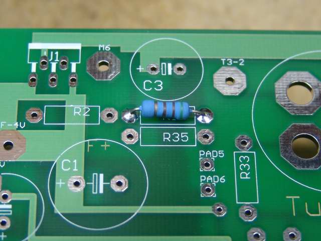 Begin by inserting, and soldering R1 as shown. Clip the excess leads from the part after soldering.
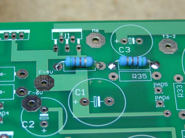 Next insert and solder R2. R2 is located next to R1. R2 is inserted, but not yet soldered in this photo.
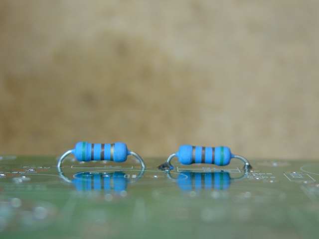 This is a side view of R1 and R2. R2 is inserted, but not yet soldered in this photo.
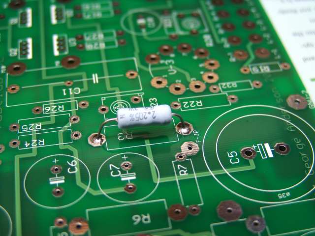 Next insert and solder R3.
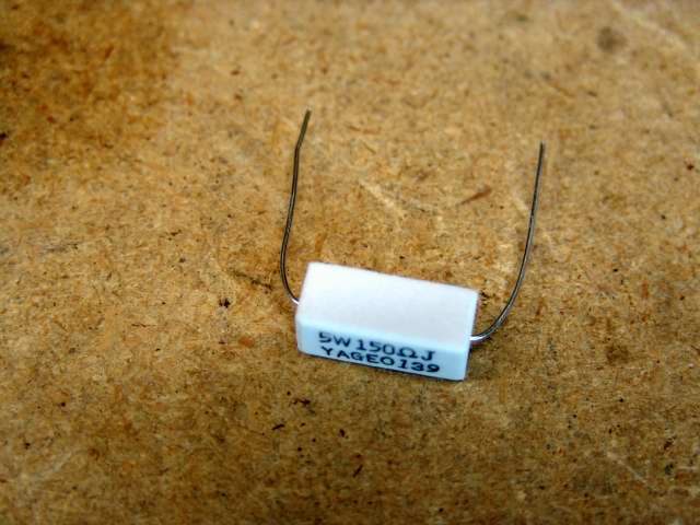 R4 is usually a large 5 watt resistor. Pre - bend its leads as shown. It may be a different part, or not used on some projects.
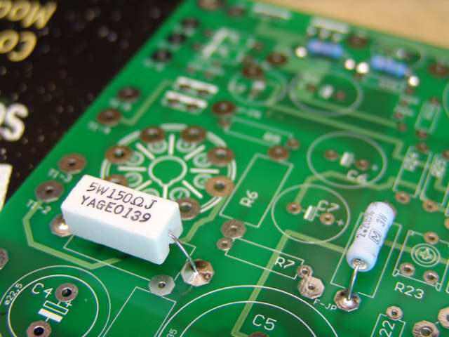 Insert and solder R4.
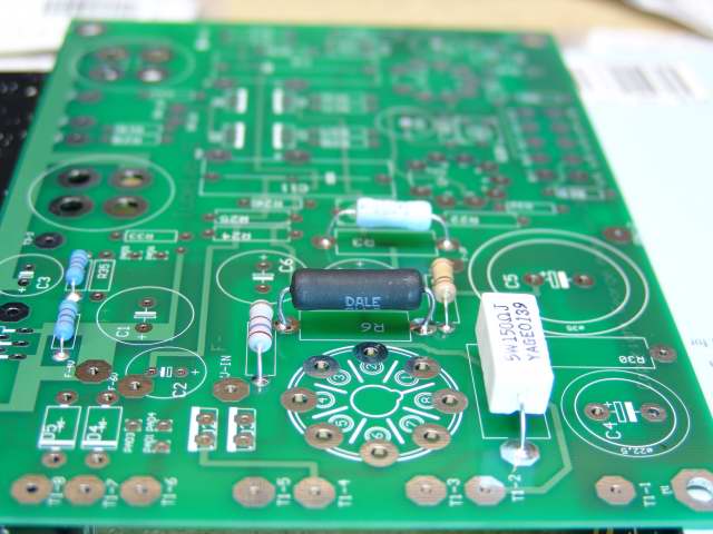 Insert and solder R5 (visible to the left of R6).
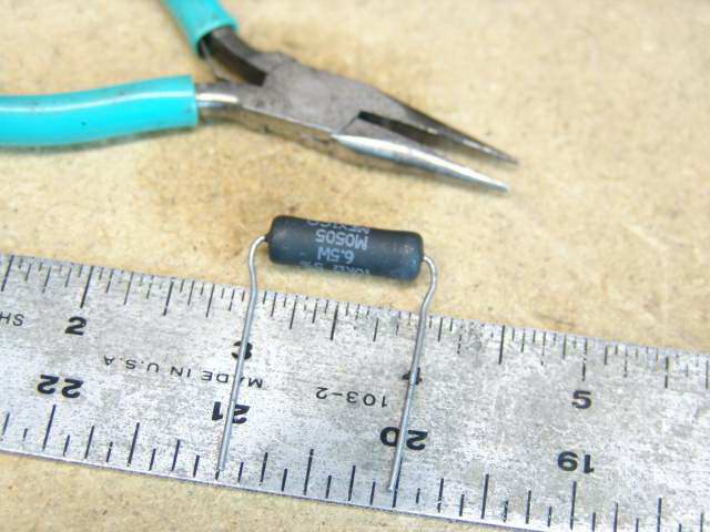
R6 has been up - rated to a 6.5 watt part after the board was laid out. Since the new part is longer than the original, the leads must be formed as shown in the photo above. Use needle nosed pliers to bend the leads to a 1 inch spacing. Avoid bending the leads directly adjacent to the part body, since this may lead to cracks. If you are sourcing your own parts, the 3 watt resistor is fine for operation below 300 volts. A 5 watt (or larger) resistor is recommended for higher voltage operation. Since the Dale 6.5 watt resistor shown here is actually smaller than the typical ceramic 5 watt resistor (like R4), it is easier to fit into the smaller space reserved for the 3 watt part.
 Insert and solder R6 followed by R7 (visible to the right of R6).
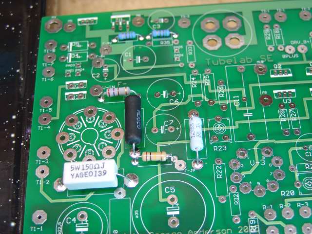 Your board should look like this at this point. Your parts may look different than these, but there should be parts in all of these places, and none in any other places.
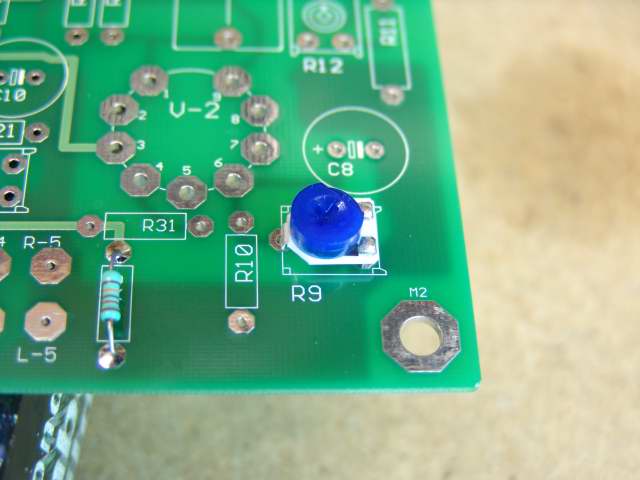 Insert and solder R8. It is the small resistor on the left.
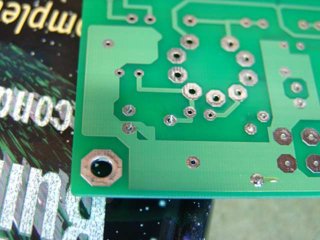
R9 is a trimmer potentiometer. There are two different values of trimmers used in this design, make sure that you have the right one and insert it into the holes in the board. It should look like the picture above before soldering. Some of these fit loose, some fit tight. If it falls out let the board sit on the book so the weight of the board holds the part in. Make sure that the part is as close to the board as it will go before soldering. Do not force it, just make sure that it is not loose or crooked. The top view of R9 is visible in the R8 photo above.
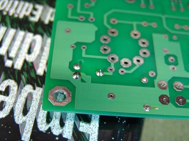 Solder R9 in place
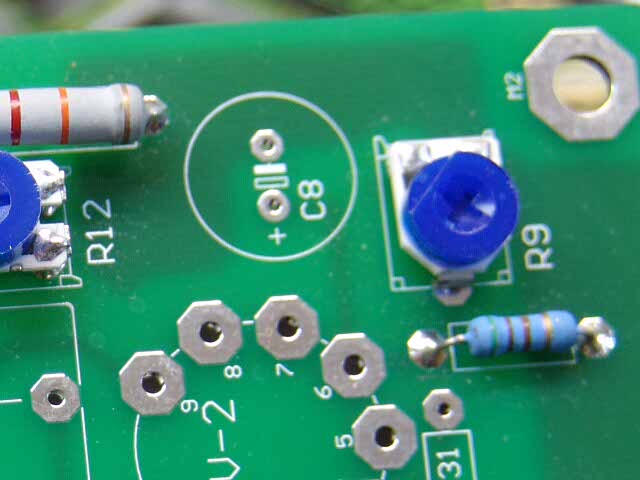 Insert and solder R10, it installs like R1, and for most designs is the same value.
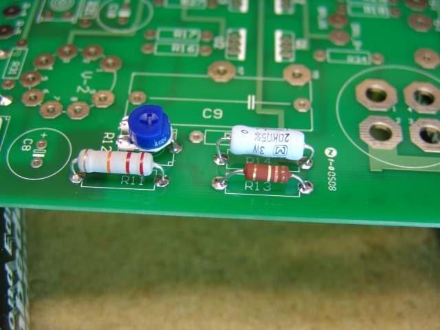 Insert and solder R11, R12, R13 and R14. R12 is a trimmer. It is a different value than R9. Your board should look like this.
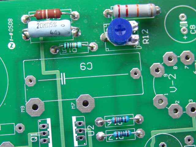 Insert and solder R15, R16 and R17. Your board should look like this.
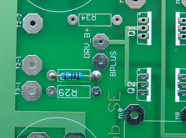 Insert and solder R18.
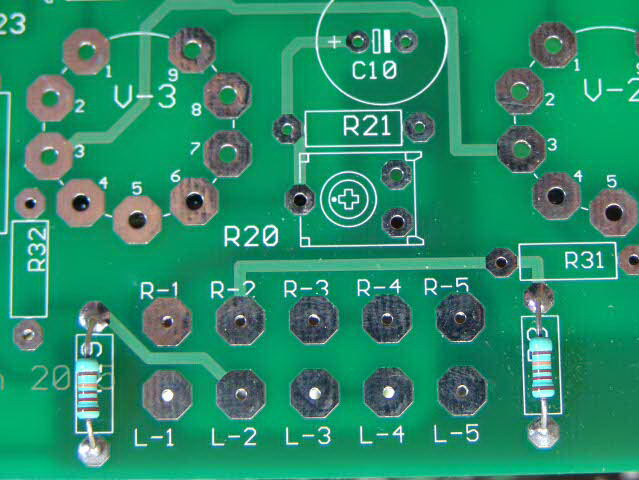 Insert and solder R19. It is the resistor on the left. (same part as R8).
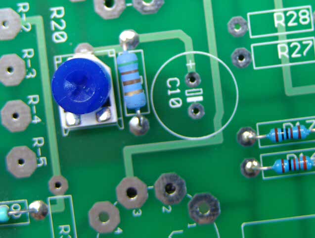 Insert and solder R20 and R21. (same parts as R9 and R10).
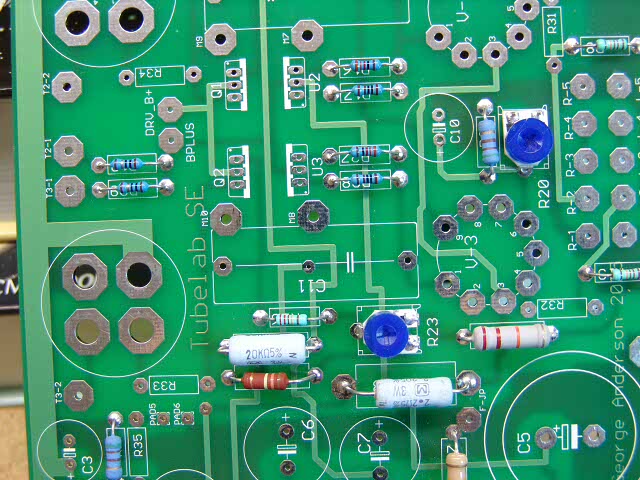
R22 through R29 are the left channel equivalents of R11 through R18. Insert and solder them in their proper location in the same manner as the ones previously installed. The above photo shows them all installed.
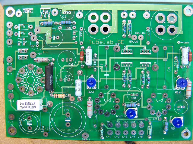 Your board should look like this at this point. Your parts may look different than these, but there should be parts in all of these places, and none in any other places.
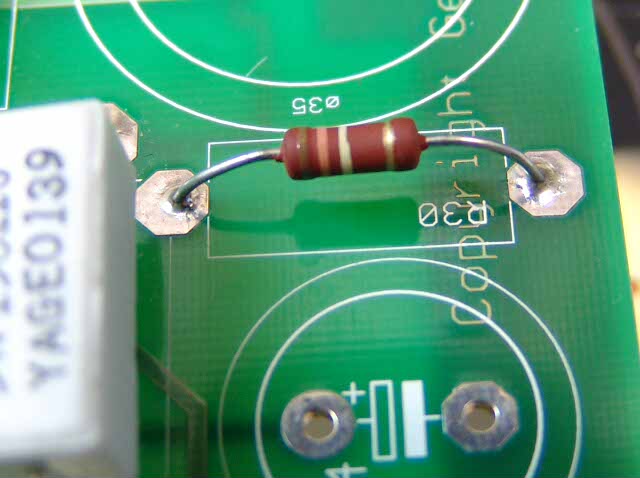 Insert and solder R30.
The R30 resistor is the bleeder resistor for the main B+ supply. In the typical amp I use a 130K 2 Watt resistor. This is adequate for most designs. If you are using a large value capacitor for C5, you may want to use a lower value resistor that is rated for a higher power. Room for a 6.5 watt resistor is provided on the board. A lower value resistor will discharge the capacitors quicker, but generate more heat. Do not go below 56K. Some users will want to install a silicon diode in parallel with this resistor. Since the negative voltage supply comes on instantly, and the positive supply is slow, there will be a slight negative voltage on C5 during this time. I have not seen any ill effects from this, but it is a reverse voltage across an electrolytic capacitor. The diode will prevent this. A 1N4007 will work fine. The diode is reverse biased during normal operation, and does not conduct. Therefore there is no reason to use a FRED or other special diode. There were no provisions in the board for this diode. It can be combined with R30 as shown below.
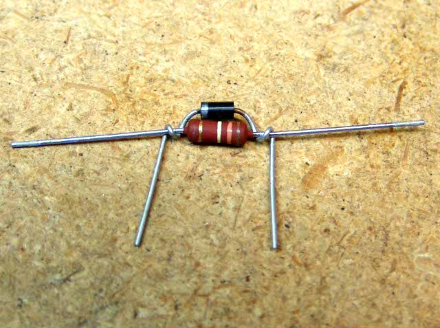 To do this, begin by wrapping the diode's leads around R30 as shown.
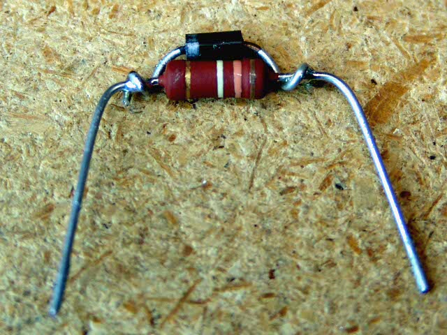 Now solder the leads as shown. Excessive heat can fry the diode. Clip the diodes leads as shown.
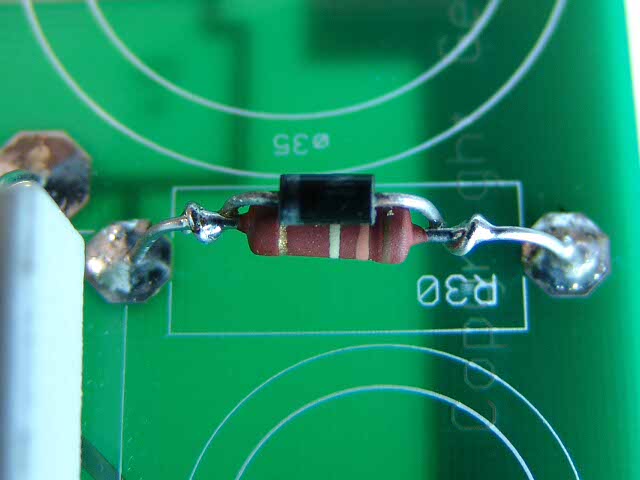 Insert the pair into the R30 position on the board. THE BANDED END OF THE DIODE MUST FACE R4.
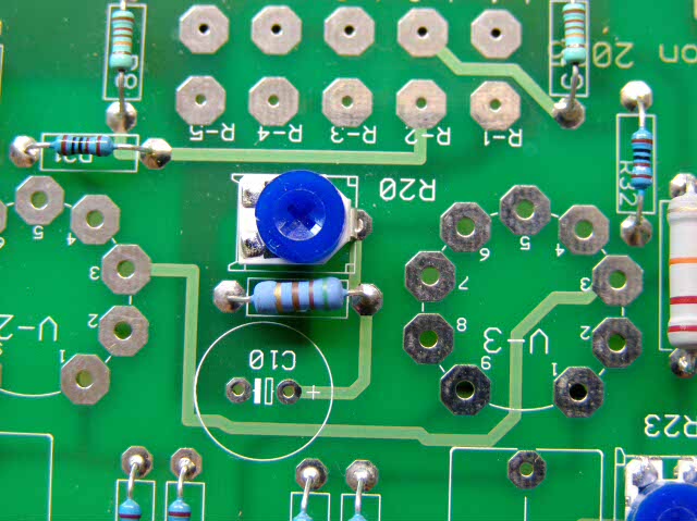 Insert and Solder R31 and R32. They are the blue ones at the left and right edges of the picture.
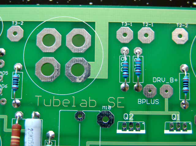 Insert and Solder R33 and R34. They are the blue ones at the left and right edges of the picture.
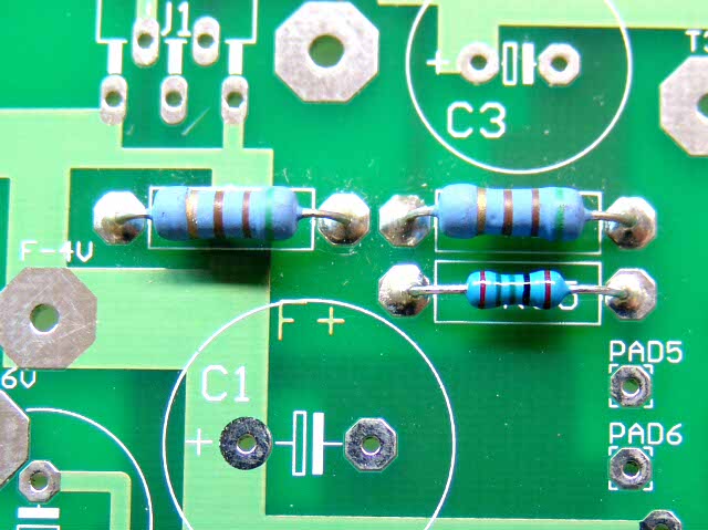 Insert R35. It is the small one below R1.
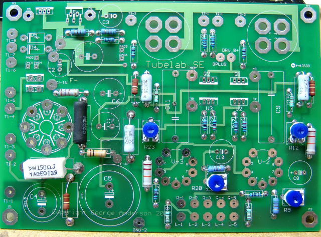
You are now done with the resistors. Please check over your board. Your board should look like the photo above at this point. Your parts may look different than these, but there should be parts in all of these places, and none in any other places. A high resolution version of this photo is included on the CD in case you need to see the details of a single part.
If your board agrees with the photo, proceed to the Tube Sockets page.