Table of Contents
- Getting Started
- Resistors
- Tube Sockets
- Semiconductors
Capacitors
- Final Assembly
- Checkout
- Setting the Bias
- Enclosures
Capacitors
Choosing the Best Capacitors for Your Amp
If you purchased a parts kit from us, you have received excellent quality capacitors. We choose a reasonable compromise between cost and performance. You can spend several hundred dollars on "boutique components" if you desire. I have built one amplifier with all high end parts and Electra-Print transformers. It did sound better than the "standard" amplifiers, but the differences were subtle. It is recommended that you assemble the amplifier using the supplied components and verify proper operation. Then you have a known "starting point" or benchmark before any modifications are made.
If you are sourcing your own components, you have the freedom to choose whatever capacitors you want that is within the size constraints of the board. In some cases external capacitors can be mounted off board to supplement or replace the on board capacitors. As with any tube amplifier the capacitors and the transformers are the most critical components in the amplifier. This is because all capacitors are far from being electrically perfect. It has been my experience that extremely expensive electrolytic capacitors are better than their generic counterparts, but not that much better than the top of the line Panasonics or Nichicons. Coupling capacitors tend to be in a different class. Here there are many opinions as to which type of dielectric material gives the best sound. I can hear a difference between some of the different types (Mylar, polypropylene, paper in oil, beeswax, etc). I can not hear a difference between some of them, although many people can. I can tell you that the cheap caps tend to sound lifeless. Choose a good quality cap that meets your budget. A brief explanation of all of the capacitors that are used in this board follows, along with the requirements for each one. This will help you pick the right part, or upgrade when you choose to start tweaking.
Some of the capacitors on this board need no special consideration. The values are the same regardless of the application of the board. C1, C2, and C3 are in the filament supply and they need no special consideration. All of the filaments operate on DC and no hum is evident. Installing super trick capacitors here will not improve the sound. C3 is directly in parallel with the filament of the output tubes. The tube's resistance is between 1/2 and 2 ohms this totally swamps the effect of the capacitors imperfections.
Capacitors C4 and C5 are however very important to the amplifier's sound and power output capabilities. Capacitor C4 is the input capacitor for the power supply. The value of this cap determines output voltage of the power supply. The larger the cap value, the higher the voltage. The value of this cap can be changed (within reason) to tweak the power supply voltage. The Amperex data sheet for the 5AR4 gives a maximum value of 60uF for this cap. This value can be exceeded at the risk of your 5AR4's lifetime. On low voltage applications you may get away with a larger value. The board can accommodate up to a 100uF 500Volt cap for C4. Some users may want to use their favorite brand of boutique capacitor here. There is a chart in the Applications page that will help you pick the value of C4. Some users will substitute an external choke for R4. This will require modifying the value of C4 to get the proper voltage, which is now dependent on the value of the choke and the value of C4.
C5 is the output capacitor for the power supply. Its value has a small effect on the output voltage. The quality of C5 has a dramatic effect on the amps sound quality. If you intend to upgrade any capacitor in the power supply, this is the one. My personal preference is to use a high quality electrolytic on the board, and connect an external (off board, mounted in the cabinet) paper in oil capacitor directly between the output transformer and the filament of the output tube. A film cap is also useful here. Details for these modifications are given on the upgrades page. I allocated the largest possible space on the board for C5. The value of this cap is not as important as the quality of the cap. Use a capacitor of at least 100 uF with a voltage rating appropriate for your transformer. Look for low ESR, inductance (ESL), and dissipation factor and make sure that it will fit in the board.
C6 and C7 are the filter capacitors for the negative voltage bias supply. Use a good quality electrolytic capacitors here. Since these capacitors get hot because they are close to the rectifier tube capacitors rated for 105 degrees C operation are a good upgrade here especially in poorly ventilated cabinets. You could also use an external film or PIO cap in parallel with C7 but I have not found a big improvement in doing so.
C8 and C10 are the cathode bypass capacitors for the driver tubes. A good quality electrolytic is needed here. A good upgrade is a tantalum cap, but these are expensive.
C9 and C11 are the coupling caps. In this design the coupling caps work into an almost purely resistive load. This makes the coupling capacitors far less critical than they are in a conventional amplifier design. It is still an important capacitor and a low quality capacitor will still have a detrimental effect on the sound. I have allocated a large space for this capacitor since some of the boutique capacitors are quite large. If your capacitors are larger than the allocated space, they may be mounted under the board, of off board. See the upgrades page for details.
Installing the Capacitors
Before we actually get down to putting capacitors on the board, I want to let you in on another secret. In the early (and not so early) days of PC board mounted vacuum tube equipment, electrolytic capacitors failed early and often. Many of these failures were caused by cheap parts operated at or above their maximum ratings. This was not always the case. It turns out that the method of mounting and installing the parts was responsible for many of the failures.
When I was working in electronics repair (1968 to 1972) I discovered another failure mode. There was a cathode bypass in the vertical output section (6LU8 tube) of most Philco (and others) TV sets that failed about once a year. Even the replacement parts failed. We tried different parts, higher voltage parts, caps with more microfarads, they still failed. They didn't short out or go open, they just slowly developed a high internal resistance (ESR) that caused the picture to shrink from the bottom. In an effort to figure this out, I actually cut open some of the failed parts, and a good one for comparison.
Most radial leaded (vertical) electrolytics are mounted directly against the board. They are then soldered from the bottom. As you are soldering the lead, it gets hot. When the lead gets hot it expands. The lead on a capacitor can grow by up to .050" while it is being soldered. If the part is pressed down tightly to the board while it is being soldered, what is going to happen when the leads cool off and they shrink back to normal length? There is already a force built into the board design that is trying to pull the leads out of the capacitor. Now, the capacitor is on a circuit board right next to a hot tube. It gets baked every time the TV (or amplifier) is turned on, and returns to room temperature every time the TV is turned off. This repeated thermal expansion and contraction will eventually tear the leads loose from the aluminum foil inside the capacitor. This is not just a vacuum tube phenomenon. Did you ever see a thin vertical line instead of a picture on an early Apple Macintosh computer. Same problem. So how do you fix this?
The simple answer is to leave some space between the capacitor and the PC board. For most capacitors 1/16" (1.5 mm ) is enough. When installing a physically small capacitor into a space meant for a larger cap (C4 and C5) leave longer leads, such that there is no stress applied to the part. If you pre - bend the leads, do not put any bend in the leads closer than 1/16" from the body of the capacitor. For large snap - in capacitors (no leads, fat prongs) this is not a problem, just insert them as intended and solder.
If you space your large leaded capacitors up from the board, as described above, they become prone to damage if the board is subject to excessive handling or drop. Since the part is now free to bend slightly the leads can be torn loose from the bottom of the cap. Don't worry, I have a solution for that too. I place a piece of thick foam tape across the bottom of the cap, with the leads protruding through it. This allows room for thermal movement, and provides a cushion for the part. It is often easier to find double sided tape. I use it and don't peel the backing from the bottom. Trim the edges to match the bottom of the cap. You may notice that most high quality capacitors already have a soft rubber cushion built into the bottom of the part, so that this step is not absolutely needed any more, but I still do it anyway. After putting the piece of tape on the bottom of the cap, insert it into the board in the normal fashion. Push the cap in until it is flush with the board and bend the leads slightly to keep it there until you solder it. If you don't want to do this for every cap at least do C6 and C7, they have to live next door to the 5AR4 and some hot resistors.
 Here are three capacitors with double sided tape cushions in place. Do not remove the backing from the tape. There is no backing on the capacitor side, but you don't want to stick the assembly to the board.
Electrolytic capacitors have a polarity and MUST be installed in the correct direction.
There is a + sign on the board silk screen near the positive connection of each electrolytic cap. All electrolytic capacitors will be marked, unfortunately they are not always marked the same. On most current capacitors the NEGATIVE lead is marked with a stripe, which usually contains a minus sign. Most also have a longer lead for the POSITIVE terminal. Some will have marking for one or both terminals on the plastic adjacent to the terminal itself. Make absolutely sure that you identify the terminals on your capacitors before installing them.
If an electrolytic is installed backwards, it WILL fail. The failure is usually an explosion, often violent, which can cause serious injury. The chemicals contained inside these caps are caustic. They are not good for people, and will eventually eat the plating off of the PC board.
OK enough talk, lets put in some parts.
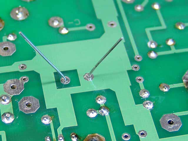 Insert C1 and bend the leads slightly to keep it from falling out. The board is placed between two books such that there is no force on the capacitor other than gravity.
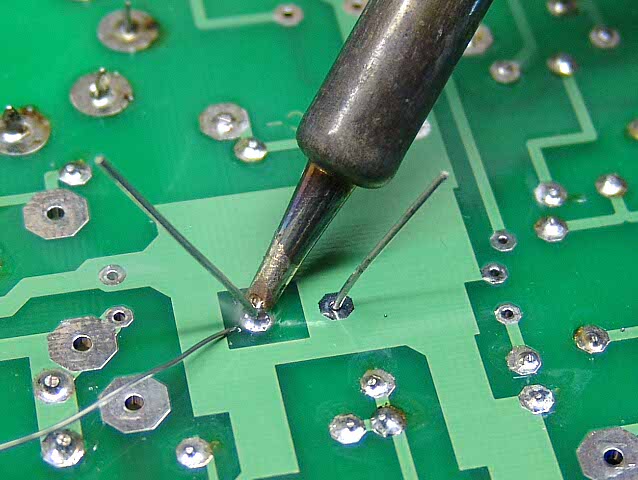 Solder C1. Take care not to apply too much solder since it can flow down the lead and cause shorts. Since you can not see the top side of the solder joint, you must judge the amount of solder by your previous experience.
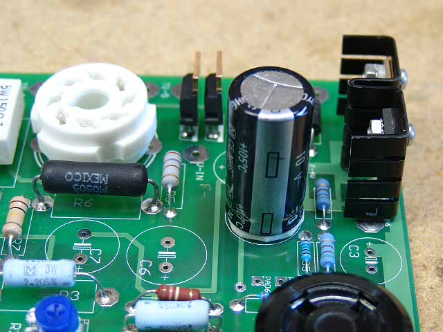 C1 looks like this when it is installed. The stripe denotes the NEGATIVE lead on the Panasonic capacitors used here.
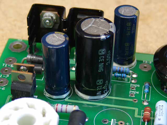 In the same manner insert and solder C2 and C3.
C4 can be a small capacitor, a large capacitor, or something in between. The holes are spaced such that a large capacitor will fit. Large capacitors often have pins which can not be bent, so the holes are spaced for them. If a smaller capacitor is used the leads must be bent slightly to fit the holes.
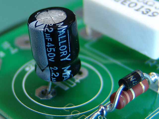 Here a small capacitor is used for C4. The leads should be gently spread such that no stress is placed on the part.
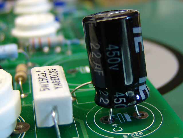 Here a mid sized capacitor is used for C4.
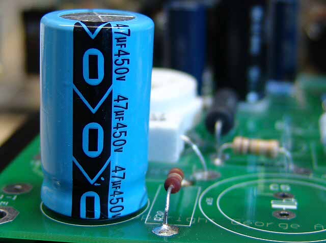 Here a large Capacitor is used for C4.
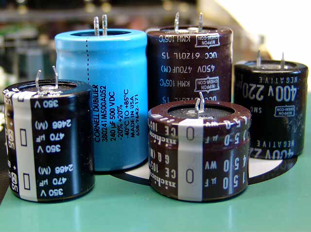
C5 is usually a large Snap - In capacitor. These are some of the types of capacitors that I have used for C5 in this board. The generic (one board fits many tube types) design uses the 470uF 350V Panasonic on the left. I use the 450 Volt Capacitors for dedicated 300B amps. I don't here much difference between any of these, but I have an oil cap in parallel with them. The 500 Volt caps are used in high voltage applications like driver boards and chokeless parafeed amps.
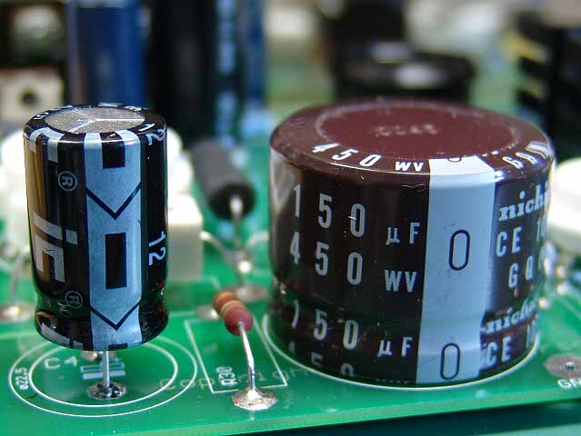 Here is C4 and C5 in the board that I have been assembling for these instructions. This board will be used for a dedicated 300B amp. It uses only 300B tubes.
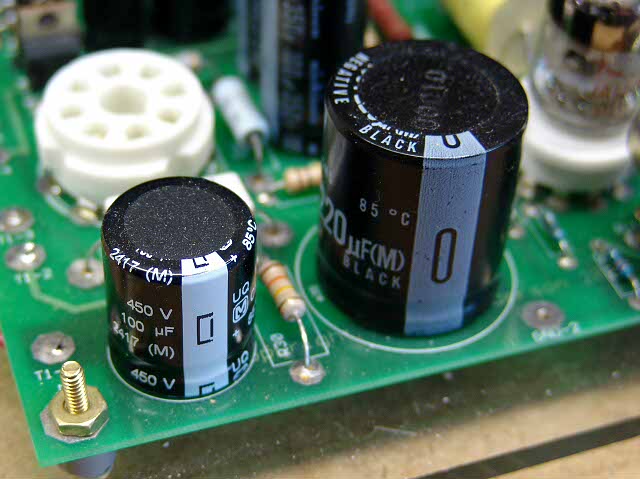 This is C4 and C5 in the Lexan amp that is shown on the opening page. Install your chosen capacitors in these locations. The negative terminal of each cap is next to the edge of the board.
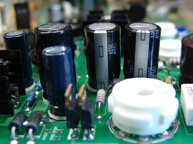 Install C6 and C7 in the same manner as the previous capacitors.
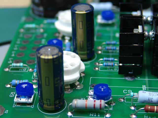 Install C8 and C10 in the same manner as the previous capacitors.
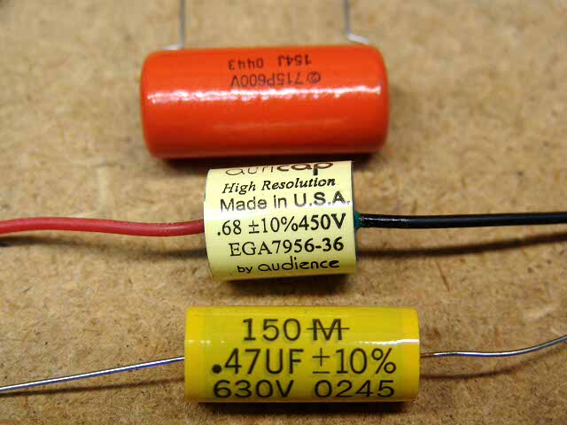 C9 and C11 are the coupling capacitors. Three different types are shown here. Bottom is a Mallory Film Cap. Next is an AuriCap. And top is a Sprague Orange Drop.
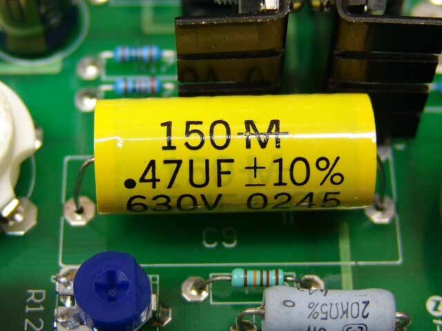 The Mallory is the easiest to install. Gently bend the leads, install, and solder.
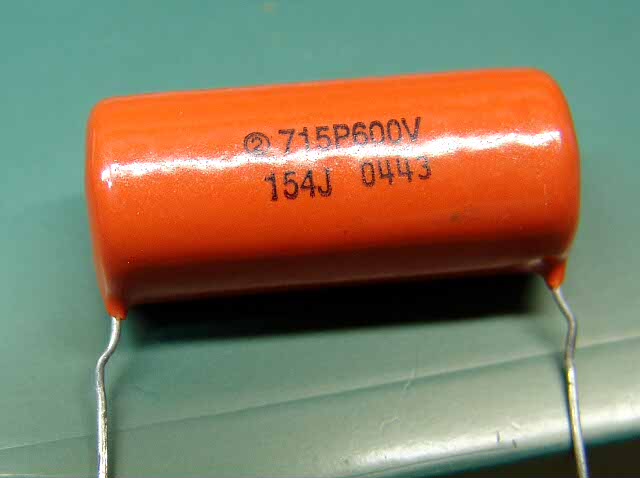 The Orange Drop is slightly harder. Using needle nosed pliers, bend the leads as shown so that the cap will drop right into the board.
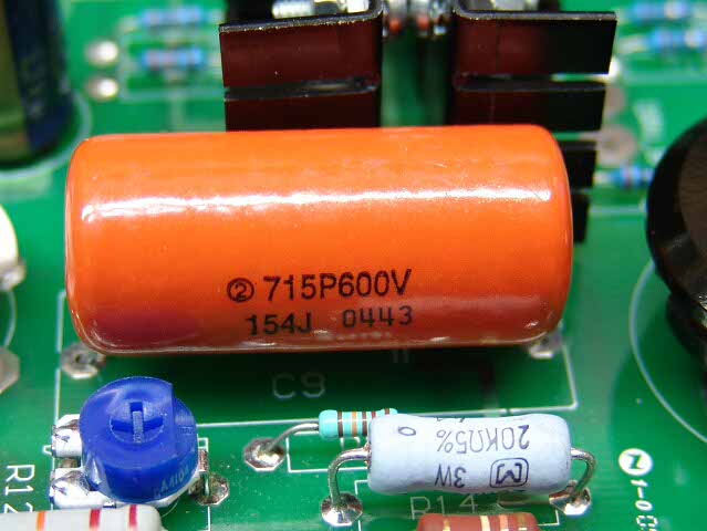 After it is inserted, flip the board over and solder.
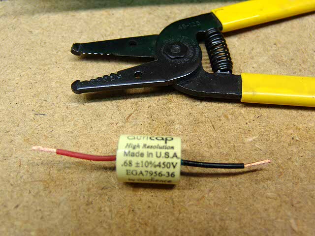 As shown in the photo further back, these caps have long flexible leads. I used the wire stripping tool to cut and strip the leads.
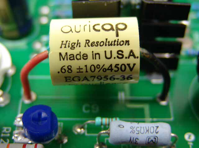 They are installed in the same manner as the other caps.
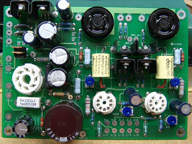 This is a photo of the board after all of the capacitors have been installed.
There are a few more items that need installation on the PC board itself. If you are satisfied with your board so far proceed to the final board assembly page.