The 845 SE is the evolution of the O2. The SE Amp Board is being used to drive a 211 or an 845 through a PowerDrive board. The amp is 95% finished (controls, and connectors not mounted yet), but quite listenable.
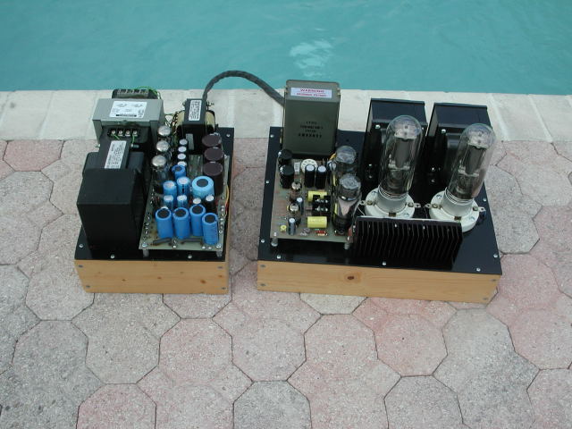 The completed amp and power supply
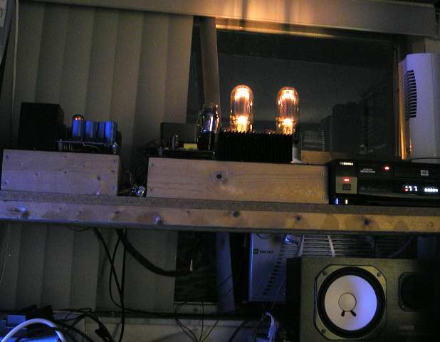 The 845SE glows in the dark
The only light in the room is the computer monitor with the blue Windows background. 845's are bright.
Background
The original Japanese Audio Note Ongaku amplifier (1991) was the ultimate single ended triode amplifier in its time. It sold for about $75,000 US Dollars for a stereo pair. It was Kondo-san's belief that the secret to exceptional sound lied in the combination of a simple circuit with exceptional quality parts. Silver wire was used in the output transformer and silver foil was used in the coupling capacitors. All other parts and tubes were of the highest quality. The schematic for Kondo's amplifier appeared in Sound Practices magazine in 1992. Audio Note UK began offering parts to build a "poor man's Ongaku". Reports from builders were favorable, but even the "poor man's" version was way out of my price range.
Fast Forward 10 Years (2002)
A friend told me that he actually started building the "poor man's Ongaku" several years ago, but never finished it. He had already sold most of the parts but he had two of the power transformers. I bought them and started collecting the other parts needed to build the amp. I started building the amplifier several years ago. I called it the O2, short for Ongaku 2. The long delay involved in getting the output transformers killed my enthusiasm for this project. The half assembled amp went into the closet and I built other amplifiers.
Fast Forward 2 More Years (2004)
I resumed this project earlier this year. First I completed the Ongaku power supply on its own chassis as originally planned. Then I prototyped one channel of the Ongaku amplifier on Tubelab 2. After listening to, and bench testing the amplifier, I decided that it didn't deliver the sound quality that I was expecting. Perhaps my less than exceptional parts were giving me less than exceptional sound. Perhaps the 12 year old design could be improved upon. Probably both. I began to analyze and test each stage of the amplifier looking for opportunities for improvement. I found two areas that needed help. The driver stage, and the power supply. I decided to use bench supplies to develop a good amplifier, then design a good power supply to run it. This is the way I usually design an amplifier. Note: The newly designed power supply is covered on its own web page.
It seems that the creators of the original design realized that the driver circuit needed some help. The Ongaku is a highly respected amplifier and many premium versions have been sold for several thousand dollars per channel. It is interesting that Audio Note (England) has upgraded their Ongaku design. From their web site: "Audio Note has completely rethought the Ongaku circuit to achieve the ultimate value for money." "The NEW Ongaku has replaced the weak sounding cathode follower with an in-house designed and manufactured driver transformer of the highest quality." The design details of their new amp are not available but it seems that them, myself and several others, have recently come to the conclusion that the grid impedance of most triodes is much lower than previously believed. This is why Audio Note has started using a driver transformer.
Jack Eliano at Electra-Print (awesome transformers) told me that he is getting 60 watts out of a single 845, and the secret is in the driver. That conversation got me thinking. I performed some simulations with SEAmpCAD from Tubecad which reveal that power levels over 50 watts (without over stressing the tube) can be achieved if you have a driver that can put out 450 volts peak to peak and source 10 milliamps. To get 50 watts you need a 1200 volt plate supply, and the grid must be driven 60 volts positive (well into A2). Distortion levels remain low at these power extremes. Tube dissipation is well within tube specifications under all conditions.
Certain tubes like the 845, 211 and the 833 (and most DHT's) need the lowest possible drive impedance and the lowest possible DC resistance in the grid circuit in order to deliver good power at low distortion levels even if A2 is never considered.
There have been several circuits "invented" to solve this design problem. I built and tested most of them. I experimented with several driver designs, MU-stage, SRPP, vacuum tube and solid state current source loaded triodes, pentodes and I even a driver transformer (UTC LS-21). Then I discovered the CCS IC. It turned out to be darn near the ideal load for a triode. I tried several different current amplifier circuits to drive the 845, pentode and triode cathode followers, emitter followers, and source followers. After giving up on cathode followers and bipolar emitter followers, I tried several high voltage MOSFETs before finding the 2SK2700. It can take 900 volts and has a relatively low gate capacitance (important). Thus the PowerDrive circuit was born. See the PowerDrive web page for a full explanation. With PowerDrive A2 operation becomes easy.
There are several myths that A2 is not good for hi fi sound. I believe that with a well designed driver an A2 amplifier can produce excellent sound that can't be distinguished from an A1 amplifier except for the additional power output. It is important to realize that an A2 amp operates in A1 for 99% of the time. In this case the original Ongaku (and the A1 design below) reach clipping at 26 watts. The final design (with PowerDrive) is just transitioning from A1 to A2 at this point. If the drive is further increased the original amp just clips harder, while the A2 amp keeps on making more power up to about 42 watts. In normal operation the two amps sound similar until a sharp percussive transient occurs. The A1 amp will clip The A2 amp does not. I find that the A2 amp does a much better job of recreating highly dynamic music which contains a lot of transients. Snare drums, rim shots, the sound of a cello being smacked sharply with the bow.
Several experiments were planned to explore A2 operation. First an amplifier was breadboarded which used CCS loads for each triode but no current amplification was used. Measurements were taken and listening tests were conducted. Then PowerDrive was added to the driver stage and testing was repeated. Finally PowerDrive was added to the input stage and testing was repeated.
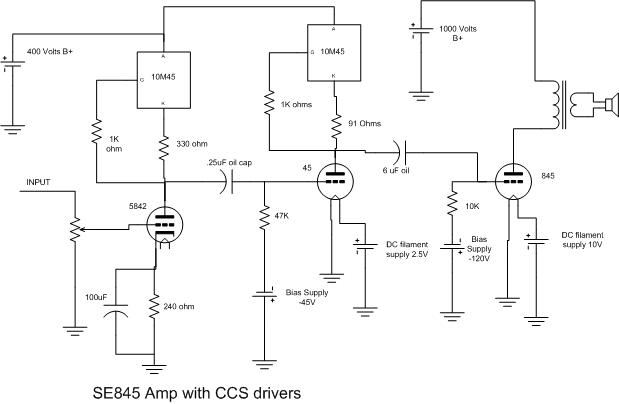
In the above circuit a relatively conventional approach is used. This design works very well as long as it is operated in class A1(no grid current is drawn). The sound is like a 45 amp only a really big 45 amp. The power output is about 25 watts at 3% distortion. The distortion at 10 watts is 1.8%. The second and third harmonics dominate up to about 12 watts then the higher order harmonics come up quickly. Most of the distortion is generated in the driver (45). The driver clips before the output stage clips.
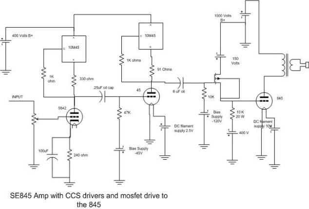
In the above circuit a MOSFET source follower (PowerDrive) was added between the 45 and the 845. The mosfet is biased at 25 mA. The grid of the 845 can swing from -300 to +60 volts (A2 operation). The limiting factor is the voltage swing available from the 45 even with no load, remember we need 450 volts peak to peak (not possible with a 400 volt supply). This design works very well and can handle A2 operation. The sound is like a 45 amp only a bigger 45 amp. The power output is about 35 watts at 3% distortion. The distortion at 10 watts is 1.1%. The second harmonic is dominant up to about 15 watts then the third shows up. The second and third harmonics are the main components up to about 25 watts then the higher order harmonics come up quickly. Most of the distortion is still generated in the driver (45). The driver clips before the output stage clips because the 400 volt supply is not high enough. 500 volts would be about right. The driver circuit clips for lack of voltage, not because it couldn't source enough current to the 845.
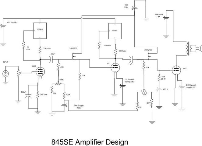
In this implementation I have added a second PowerDrive circuit between the input tube (5842) and the 45. Even with the known driver limitations I get almost 40 watts at clip. I performed the usual testing with unreal results. Distortion at 10 watts is 0.88% and is almost all second harmonic. The amp is purely A1 at this point.
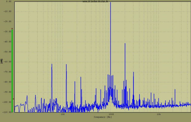
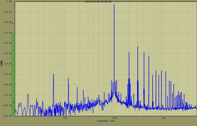
Distortion at 30 watts is 1.22%. The amp is well into A2 with the grid voltage reaching +30 volts on peaks. Now the higher order harmonics begin to show. I had to turn up the power to 37 watts to reach 5% distortion. Hard clip occurs at 39 watts. The grid voltage reaches +52 volts at this point.
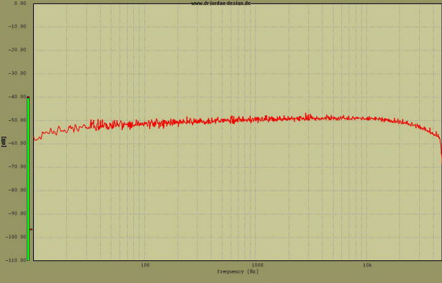
The frequency response at 10 watts doesn't look to bad either.
The amp design is finished. The entire amplifier circuit (one channel) was developed using Tubelab 2 without touching my soldering iron. I experimented with several driver designs, MU-stage, SRPP, vacuum tube and solid state current source loaded triodes, pentodes and I even a driver transformer (UTC LS-21), all right here in one weekend. Now that the hard part is done, the design will be committed to a PC board. Usually I keep the breadboard design intact until the final design is done, but the transformers will be mounted to the chassis soon.
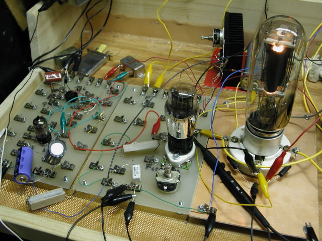
Tubelab breadboard of the SE845, prototype PowerDrive circuit is mounted to the heat sink behind the tubes
Update
A new power supply was designed to give this amp what it really wants, more voltage. The new power supply really wakes up the sound, adds life and punch to the music. Power goes up a few watts, to over 40 watts at 3%.
When I designed the PC board for the Simple 45 I had planned on using the same board for the driver in this amp. I already had one built and tested. The only new board needed was the PowerDrive board. The circuitry on this board dissipates about 40 watts so a suitable heat sink must be used. I laid out the board, and built one.
Now that I have all of the blocks in this puzzle I put it together. The chassis plate for the Ongaku was completed several years ago. So was the wood base, although I plan to build a new base someday. I mounted all of the parts, wired it up, and then turned it on. It worked great the first time, and has been playing almost every day since. The volume control, power receptacle, input jacks, and speaker posts are still not mounted yet. I have been listening to this amp for a month with temporary connections.
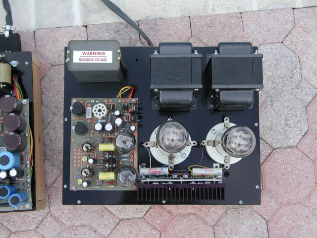 Top view of the amp
The pictures of the power supply are on the 845 power supply page.
Under The Chassis - Not Much Going On Here
As usual with my designs there are no parts under the chassis on the amplifier. The two transformers and a choke on the power supply would have been on top, but since I re-used the old Ongaku chassis, there wasn't enough room to put all the iron on top.
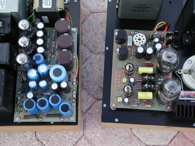 The power supply board and the amplifier board
In both cases, all of the action takes place on the circuit boards. The empty octal socket on the amplifier board is occupied when the board is used in a stand alone application.
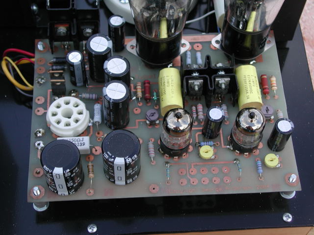 Close up of the Driver Board
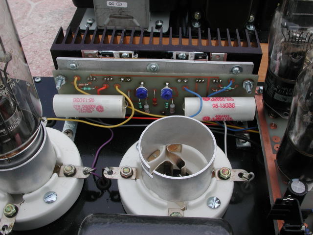 The PowerDrive Board mounted to a large heat sink
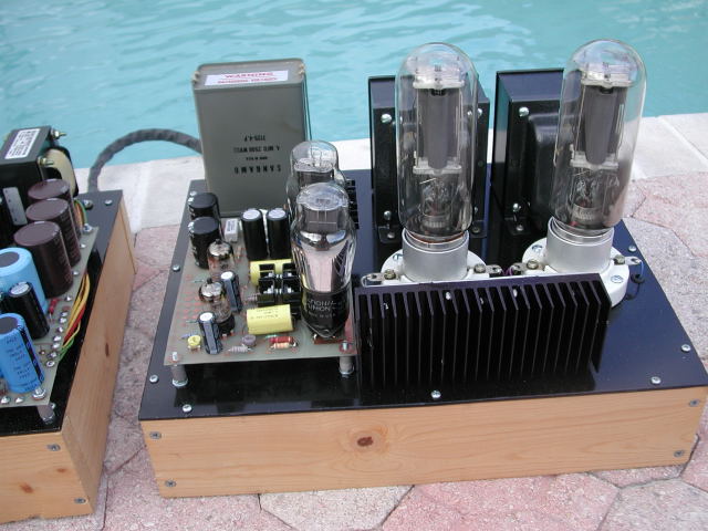 Another view of the completed 845 amplifier
Tweaking the 845SE
Over the years I have collected 7 old untested 845's and 3 211's. I have 4 new Chinese 845's and 2 new Chinese 211's, I also have a box full of 45's and 6 2A3's. Over the Thanksgiving week (5 days off from work, and my wife is out of town) I did some tweaking on the 845SE amp. I tried 15 different output tubes (211's and 845's old stock and new Chinese) and 21 different driver tubes (old 45's, RCA and Chinese 2A3's). I also tried 3 different types of coupling caps in the PowerDrive board. I did not change the Wonder Caps on the Driver board.
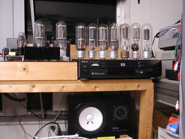 My collection of old 845's and 211's (New Chinese tubes not shown)
First I tried all of my 845's and then I tried all of my 211's. Each tube was biased at 60mA and 75mA. The grid voltage required to achieve the stated current was recorded. The transconductance for each tube was calculated from this information. In this manner the tubes can be matched in the actual amplifier. A matched pair of RCA 845's, a matched pair of Chinese 845's, and a matched pair (close) of Chinese 211's were selected. The pair of Chinese 845's were the tubes used to design and test the amplifier. They were purchased from Triode electronics as a matched pair, and were well matched. I had 3 RCA 211's but one turned out to be extremely gassy and could cause severe amplifier damage. The second one was weak and did not sound good. RCA 211's were not evaluated for this reason.
The 45's operate on a constant current source IC so they could only be matched by grid voltage. I came up with a matched pair of RCA 45's a matched pair of Tung Sol 45's , a matched pair of RCA 2A3's and a pair of Chinese 2A3's. I also have several 45's and 2A3's that do not have a matching tube.
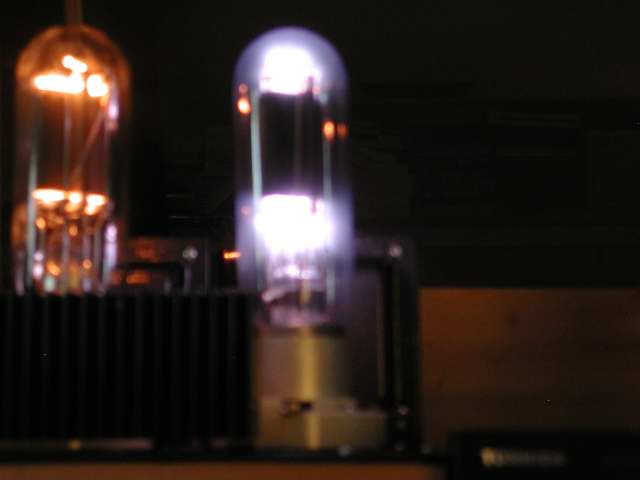 A very gassy 211 - read the warning below.
I took this picture in a big hurry, so it is blurry. I had to shut the amp off before damage could occur. This situation is a tube arc waiting to happen. Plate current was over 300mA and climbing. This would have killed a wimpy power supply and can fry an output transformer. A loud hissing and crackling sound emanated from the speaker just as I hit the master kill switch. If you see a purple glow like this inside (between the elements) a vacuum tube it means that the tube has an abnormal gas inside (usually an air leak). TURN THE AMP OFF IMMEDIATELY! A glow like this is normal in a gas tube like voltage regulator tubes (0A2, VR150 etc). A BLUE glow that appears ON THE GLASS of a vacuum tube is a normal condition.
After the above picture was taken, the amp still seemed to work normally, so testing continued. After testing for a while, I noticed a tendency for the bias to drift in the right channel. The situation grew worse with time, so I decided to investigate. It seems that the purple glow that caused the cathode current to shoot up to over 300mA also caused an unknown amount of grid current to flow. This caused damage to the MOSFET in the right channel PowerDrive circuit. It should be noted that most solid state devices are either good or bad, but it is possible for a MOSFET to be partially fried. This happens when the Metal Oxide layer gets damaged. This is usually caused by static electricity, but an 1100 volt arc to the grid will do it too. The MOSFET was replaced and testing continued.
While the PowerDrive board was unmounted the GE coupling caps were upgraded. I had purchased a large bag of the GE caps cheap on Ebay. I had intended on using them for power supply caps, but they were the only 600 volt rated caps that I had when I built the amp. I ordered some better parts from Antique Electronics Supply. At first I replaced the GE's with Solen fast caps. The amp was then auditioned with the same tubes that I had been using all along. I then replaced the Solen capacitors with Hovland Music caps. The amp was auditioned again with the same tubes. To be honest I did not hear much improvement with the Solens. The Hovlands seemed to sound better but I couldn't tell you what the improvement was. If I had the time I would have put the GE's back in for a direct comparison. On to the tubes!
I tried each pair of output tubes at different bias current settings from 50 to 90 mA. I ran the current up to 120 mA on the Chinese tubes. Yes I know this is an idle dissipation of over 130 watts per tube, well above the maximum rating but these tubes seem to sound better that way and they are replaceable and relatively cheap (I found them for $28 each). I would never try this with the old tubes. The amp was auditioned with each set of tubes for a couple of hours with various types of music. Then basic bench testing was performed.
The answers will have to wait for now
During the testing I discovered a problem with the amplifier. The amplifier probably had this problem all along, but it is magnified with the RCA 845's. What I found is a strange type of distortion that appears only when both channels are driven into clipping. It sounds like a crackling sound on bass notes. Either channel can be driven well into clipping and this does not happen. This can be verified with bench testing. A strange notching of the waveform appears at the crest of the sine wave. Intermodulation products appear rapidly at the onset of this distortion.
With the Chinese 211's the distortion does not appear even when the amp is driven into hard clipping. With the original Chinese 845's the distortion appears only when both channels are driven well into clipping. With the RCA 845's the distortion shows up before the amp clips, however both channels must be driven hard. Bias current affects this distortion, but not much. Choice of driver tube also makes a difference, but not much.
Until this anomaly is sorted out, any tube comparison will not be valid. The amp still sounds great, up until the point of clipping.
Update
I had the opportunity to test this amp with the power supply that I used to prototype the 833A SE amp. The crackling sound does not occur with this power supply. This points to the power supply as the source of this anomaly. Since the amplifier sounds great at any normal volume level, I have not been motivated to find the source of this distortion, but I will probably build a new power supply when I have the time.