PowerDrive has generated more email than anything else on this web site. At first the email was mostly negative, often blasting me for corrupting their tube designs with "sand". I even got one suggesting that I change my name to Transistorlab! After a few adventurous souls actually built their own PowerDrive circuits, listened to them, and reported their results of some of the forums, the email began to change. Now it mostly reads like " I need a PowerDrive circuit to drive a XXXX tube from a YYYY tube, can you design me one". I get 2 or 3 of these a week. Some have offered to pay me for the design. This would be great if I didn't already have a full time engineering job that demands 50 hours a week. There is no way that I have time to do this (especially with all the other stuff that is going on), so I am doing the next best thing. I created a new page that will help you design your own PowerDrive. It is on this web site here.
Background
It is not unusual for music to have transient peaks 20 db above the average power level. Transients 10 to 15 db above the average power level are fairly common. This means that if your average listening level is 1 watt, your amplifier will be called upon to produce up to 100 watts on peaks. If you only have a 10 watt amp, it will clip the signal on the transient peak. If this is all that happens you may not even notice it. However, this is not all that usually happens. Often there is some distortion that lingers after the transient has passed. This distortion can originate from several sources.
If an amplifier uses a large amount of global feedback, the amplifier may have a finite recovery time for the loop dynamics to settle out after a temporary overload has passed. What is wrong with a lot of feedback? Simply put, at the instant an amp clips its gain drops toward zero (an increasing input voltage produces no more output voltage) and the feedback attempts to correct this situation by essentially cranking up the gain thus driving the amp further into clipping. There is a time delay for the system to recover, during which the output does not resemble the input. The greater the amount of feedback the greater the problem. And this is with a purely resistive load. Drive a speaker and the feedback network could be trying to correct for things external to the amp. Often distortion of this type produces higher order harmonics, intermodulation products, and non harmonically related signals that tend to sound terrible. This can occur with a solid state or a vacuum tube amplifier. Most modern solid state amplifiers tend to use a lot of global feedback, so they tend to sound gross when operated into clipping. The current trend is to simply build a bigger amp in an attempt to avoid clipping altogether. Most vacuum tube amplifiers use limited amounts of (or zero) global feedback, which tends to reduce this type of distortion. There is however a type of overload that is usually particular to vacuum tube amplifiers.
Blocking Distortion
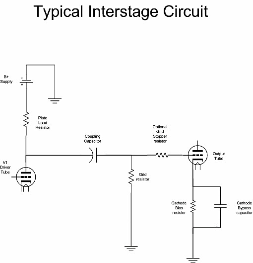
A problem exists in all vacuum tube power amplifiers when the input signal reaches the point where the driver tube attempts to drive the grid of the output tube positive. You say that your amp operates in A1 and that won't happen. Wrong! Unless the driver is carefully designed to clip before this can happen, it will. It has been my experience that clipping is less obvious sounding if the output stage clips first, and the amplifier is set up so that the clipping is symmetrical (equal clipping on the top and bottom of a sine wave). Refer to the typical interstage circuit below to understand this phenomenon:

For this discussion, assume that the plate voltage on the driver tube is 100 volts, the output tube grid is 0 volts, and the output tube cathode is 10 volts (numbers chosen for easy arithmetic). Assume that the driver plate load resistor is 50K and the output tubes grid resistor is 200K and the coupling cap is .1uF. As long as the driver tube's output signal is below 20 volts peak to peak, everything works as expected. The coupling cap is charged to 100 volts, and no current is flowing in or out of the output tubes grid. If a large enough positive going transient appears at the input of the amp, the driver tube will conduct heavily generating a negative going pulse at the driver plate. This will be coupled into the grid of the output tube driving it toward (and possibly into) cutoff. The output tube may go into a non linear region, or be cutoff entirely for an instant. This will cause temporary distortion due to clipping. Since the output tube's grid is driven negatively, no grid current flows, and equilibrium is maintained.
A large enough negatively going transient at the amp input is a different story however. This transient causes the plate voltage to rise in the driver tube. This rise is coupled to the grid of the output tube. As long as the positive going pulse at the output tubes grid does not overcome the 10 volts of bias, no grid current flows, and equilibrium is maintained. If the positive pulse does exceed the 10 volts of bias, the grid of the output tube goes positive with respect to its cathode. As the grid goes positive it draws current. The amount of current varies depending on the type of tube and the magnitude of the positive voltage. It is possible for some tubes to draw hundreds of milliamps of grid current with 50 volts of positive voltage on the grid. The grid - cathode interface acts like a vacuum tube diode, capable of clamping the grid voltage to a few volts more positive than the cathode. Most tubes will actually begin to draw some grid current when the grid is still negative by a volt or two. If the driver can not source any current into the grid of the output tube, distortion will occur as the grid approaches zero volts. It gets worse!
Consider an extreme case. A large negative going transient hits the input of the amp causing the driver tube to be cutoff. The plate voltage rises quickly from its quiescent value of 100 volts. The grid voltage of the output tube begins rising but as it tries to go above the cathode voltage (10 volts) it is quickly clamped at a few volts positive. At this instant all of the current that was flowing into the plate of the driver tube is now flowing into the coupling cap. Since the other end of the coupling cap is effectively clamped at say 15 volts, the cap is being discharged. The time constant of this discharging is determined by the plate load resistor, and the coupling capacitor value. If the transient lasts long enough, the capacitor will no longer be charged to 100 volts. We will assume that it now contains 99 volts. Now if the transient is removed, the amp attempts to recover. The driver's plate voltage returns to 100 volts, but some of the charge in the coupling cap was lost, so the output tube's grid is now at -1 volt. If there are no more transients the capacitor will recharge through the output tubes grid resistor. But now the time constant to recharge the coupling cap is determined by the driver's plate load resistor PLUS the output tubes grid resistor and the coupling caps value. In this example the recharging time constant is five times longer than the discharging time. This is typical. The amp may distort a normal signal during this time. The bias will be shifted toward cutoff during the recovery time. This may only cause distortion on large signals in a SE amp, but could result in crossover distortion in a push pull amp. If the transients come often enough the effect will be cumulative since the coupling capacitor never has the time to fully recharge. These "extreme cases" happen all the time in a guitar amp. The resulting blocking distortion can cause the amp to actually block a signal after an extreme overload. This is known as "farting out" to a guitar player. Blocking distortion is usually accentuated by global feedback.
How can this be fixed. The obvious solution is to reduce the value of the grid resistor in an attempt to equalize the two time constant. This also lowers the load impedance seen by the driver tube, reducing its gain and increases its distortion. A not so obvious solution is to increase (or install) the grid stopper in the output stage. This limits the current that could be drawn by the output tube. This will reduce the high frequency response particularly if the output tube is a triode. It usually helps to use the smallest coupling cap to give the required low frequency response. These tricks can help in mild cases, but what we really need is a driver topology that can feed the output tube's grid more current than it can eat!
This requires a driver with a low output impedance. Ever since the drawbacks of RC coupling were documented by Crowhurst over 50 years ago vacuum tube designers have been looking for a better driver circuit. The two most popular circuits are the cathode follower and the interstage transformer. A good interstage transformer is hard to manufacture due to the high impedances involved and the need for wide bandwidth without phase or amplitude distortion. Good ones do exist but they are expensive. Cathode followers have always invoked a "something is missing from the sound" experience. I offer another alternative, PowerDrive.
What is PowerDrive? PowerDrive is an interstage coupling circuit designed to present the driver with a very high impedance from DC to daylight and provide a very low impedance to the output tube's grid from DC to beyond 100 KHz. It can source all of the current that the grid can draw and produce enough voltage to drive the output stage into clipping at all audio frequencies. The driver and interstage circuit is lo longer the limiting factor when building big triode amplifiers.
How is PowerDrive better than a cathode follower or a transformer? This circuit was invented because I didn't like the performance of the driver circuit in the Ongaku amplifier that I had built on Tubelab 2. I spent years collecting the parts to build a "Poor man's Ongaku" from a schematic in and old issue of Sound Practices magazine. This is a highly regarded audiophile design. The Ongaku design uses a 6072 (12AY7) in SRPP configuration followed by a 5687 cathode follower driving a 211. I built one channel of this amp on Tubelab 2 and the power supply (using the Audio Note transformer) on its own chassis since I had intended it for use with the Ongaku amp. I tried this amp with the intended 211's and 845's since they have a better reputation in the audiophile world.
The results were not what I expected. With simple music through the 211's it sounded pretty good. Loud rock sounded bad and heavy metal (Metallica) sounded worse. At full volume (clipping observed on the scope) the amp produced rude sounds that weren't on the CD. For the ultimate test I plugged in a guitar preamp (ADA MP-1) and cut loose while watching the 211's grid on the scope. Sounded gross, looked worse. Transient effects could drive this amp nuts and the cathode follower was primarily to blame. Note: Some of these ill effects were later traced to the power supply. I had one scope probe on the output of the SRPP stage and the other on the 211's grid. The waveforms should look the same. They did not. I tried several other 9 pin tubes. None could drive the grid more than 4 or 5 volts positive. The 7044 was the best. The cathode follower stage could not deliver the current needed to drive the grid of an 845 or a 211 into the positive region. Game over, the Ongaku was not to be. (Kondo-san warned that the amp would not deliver unless exceptional parts were used). I am guessing that he never tried to play Metallica with the volume control all the way up either.
I experimented with several driver designs, MU-stage, vacuum tube and solid state current source loaded triodes, pentodes and I even a driver transformer (UTC LS-21). Then I discovered the CCS IC. It turned out to be darn near the ideal load for a triode. I tried several different current amplifier circuits to drive the 845. After giving up on bipolar emitter followers, (Safe Operating Area failures, especially with the guitar preamp) I tried several high voltage MOSFETs before finding the 2SK2700. It can take 900 volts and has a relatively low gate capacitance (important). The PowerDrive circuit was born. I had already been developing the SE amp board, so I simply connected the PowerDrive circuit between the SE amp and the 845 tube. This is how the 845SE came to be. This amp is unreal, Metallica, Pink Floyd, no problem. The guitar preamp through this thing sounds like a really big black face Fender Champ. It sounds so good that I will probably build an 845SE guitar amplifier in the future.
To be honest I didn't give the driver transformer option a fair chance since I only have one of them and they are expensive (over $100 each on Ebay). After hearing, and testing the 845SE with two PowerDrive circuits (one for the 845 and one for the 45) I don't plan on using transformers.

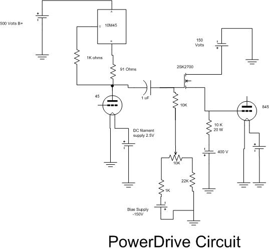
What is all of this? The circuit can be broken down into two sections. A constant current source IC (10M45) is the load for the driver tube, and an FET source follower is the current amplifier (replacing the cathode follower). The FET can operate at a bias current of 20 to 100Ma (much more than a vacuum tube cathode follower) which insures a low driving impedance for the output tube. The PowerDrive circuit was designed to satisfy these three conditions which were not fulfilled by previous driver circuits.
- The ideal load for a triode is a constant current. The constant current source IC (10M45) provides this at DC. The 91 ohm resistor sets the current (30 mA) and the 1K resistor prevents oscillation.
- This is only half of the triode's load. We must also consider the AC load that the triode sees. In this circuit the triode sees (assuming a perfect coupling cap) at least 11K, the 10K resistor connected to the gate in series with the 1K resistor (later revisions use higher resistor values) in parallel with the fet's gate to drain capacitance. For a 45 this is an easy load to drive. It usually sees a 5K transformer with it's associated capacitance and inductance.
- The ideal source for the output tube's grid is zero DC resistance and zero AC impedance. The DC condition can be considered in two cases. The first is when the driver is sourcing current to the grid of the output tube. In this case the grid sees the on resistance of the fet in series with the dynamic impedance of the 150 volt power supply. The fet we use is six ohms (a vacuum tube cathode follower is several thousand ohms and not constant) and the power supply should be a few ohms. The second condition is when the grid transitions back negative and the driver must "sink" the tube's grid current. The driver must also be capable of discharging the miller capacitance at the tube's grid quickly. In this case the grid sees the 10K resistor from the grid to the negative supply. The DC conditions have been verified to hold true up to about 500 KHz, well beyond the capabilities of the driver tube.
Circuit Testing
I did some testing on the small PowerDrive circuit used in the Tubelab SE. The 5842 has an amplification factor (Mu) of 50. This means that under IDEAL conditions (infinite load) the tube could deliver a maximum voltage gain of 50. In practice the voltage gain will always be less than 50, usually much less. The gain will also vary with frequency. I measured the voltage gain of the 5842 stage on each iteration of the Simple 45 amplifier design. The original amp (not documented) used an RC coupling scheme. The stage gain for the 5842 was 22, and began to roll off at 30 KHz. The first documented version (with the constant current diodes) had a much higher gain of 32. The version with the transistor current source measured 35 and the IC current source measured 39, with gain roll off at 65 KHz. The PowerDrive version has a stage gain of 45 and the gain is flat to beyond 100 KHz. The measurement limit of my HP8903 audio analyzer. All testing was done on a working amplifier with a 45 tube as a load (real world conditions).
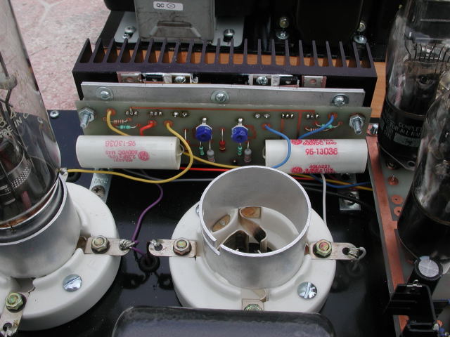
 Here is the PowerDrive board as used in the 845SE
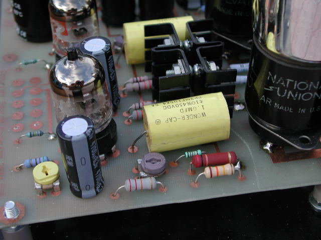
 Here is the smaller PowerDrive circuit used on the SE amplifier board, which is used as the driver in the 845SE amplifier
Update 1
I designed the power drive board for use with the 845 tube. It went into the 845SE amplifier and performed flawlessly for over a year. I had a custom transformer built for an 833A amplifier project. I had promised to quickly evaluate it when the first transformer (of 4) was built. When the transformer showed up, I needed an 833A amp quickly. What do I do? I wired an 833A tube into the 845 amp using vise grips and hose clamps for a socket. In the quest for more power, I wired in a power supply from a Motorola base station transmitter. What does all of this have to do with PowerDrive? Plenty! During all of this testing the unmodified PowerDrive board cranked over 100 volts peak to peak into an 833A tube operating in heavy A2. This tube draws over 100 milliamps of grid current on peaks under these conditions. A mere mortal driver circuit would severely distort or blow up under these circumstances. I subjected the driver (and the whole amp) to about two hours of my guitar playing at full blast (hard clip), which could kill any wimpy amp, without incident. I use this as a reliability test.
The frequency response of the drive path (from amp input to the grid of the 833A) was was from 11 Hz to 345 KHz within 3 db. The response was within 1 db from 21 Hz to 240 KHz, and no phase shift was observed over this range. All of this was measured while driving an 833A to full power. Distortion of the entire amplifier measured 0.93 % at 50 Watts when operated at 1KHz. This rose to 5% at 221 Watts RMS. For full details see the 833A amp page.
Find me a transformer that could do this using a 45 tube for a driver! PowerDrive works, people!
Update 2
It has been almost three years since I wrote the original PowerDrive page. I have experimented further with vacuum tube CCS circuits, and high performance cathode followers. These circuits have found use in a few applications. Others have documented a possible source of phase distortion in the PowerDrive circuit caused by the voltage varying capacitance effect in all solid state devices. The capacitances in the CCS IC and the mosfet will change slightly with the signal voltage. This presents the driver tube with a varying capacitance in parallel with its load. This could lead to possible phase distortion. Means to reduce this are explained on the PowerDrive cookbook page. I have also designed a PowerDrive circuit containing no solid state devices. It is also shown on the cookbook page. I measured the performance of both circuits, and the solid state version tests better, but we have all heard this before, so I did some listening tests. I prefer the solid state version and so do most listeners.