Note
This board has not been mass produced and probably won’t be. The demand for this board is not high enough for affordable duplication. This has proven to be a good low cost power supply, but I have discovered that better sounding power supplies exist. See the update at the bottom of the page.
The 845SE amplifier was designed prototyped and built using the Ongaku power supply. From the beginning I was not happy with the performance of this power supply. First of all it requires a rare and expensive Audio Note transformer (I have two, and will likely put them on Ebay). The power supply was built from the schematic published in a 1992 edition of Sound Practices magazine, In fact I breadboarded (on Tubelab) one channel of the complete amp. What's wrong with this power supply? Frankly the regulation SUCKS! 990 volts with no load, and 902 volts with ONE channel connected and biased at 80mA. That equates to an internal impedance of over 1000 ohms at DC (resistance). Measured resistance of the transformer secondary is 210 ohms, the filter choke is 90 ohms. That leaves 700 ohms unaccounted for. Most of that is in the rectifier tubes. Since the DC resistance is so high, the output impedance of the high voltage supply is dominated by the dynamic (frequency dependent) impedance of the (electrolytic) capacitors across the output. This is in the signal path on an SE amp. Unfortunately that is not all, since the 460 volt supply for the driver is derived from the same transformer winding there is inevitable frequency dependent coupling through the power supply from the output stage to the driver stage (otherwise known as FEEDBACK). There is also coupling from one channel to the other.
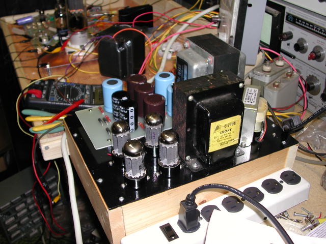
 The Ongaku Power Supply with the 845SE breadboard in the background
I decided to design a new power supply that would solve this problem, generate the voltages required by PowerDrive, and use only catalog parts (no custom wound transformers). I also want more power, which requires more voltage. Obviously I would want a lower output impedance. Also zero coupling between the output stage and the rest of the amp. That implies separate power supplies. Also I dislike hum, so I want DC on all of the filaments. All supplies should come up in the proper order without user intervention.
OK, first we state all of the required voltages:
| 1000 to 1200 volts at 200 milliamps | HV supply for the 845's |
| 450 to 500 volts at 75 milliamps | B+ for the driver board (45's and 5842's) |
| -400 volts at 60 milliamps | Bias supplies (high current for PowerDrive) |
| 2 X 10 volts at 3.25 amps (floating) | Filament supplies for each 845 |
| 6.3 volts at 0.5 amps | Filament supply for 5842's |
| 2.5 volts at 5 amps | Filament for 45's with capacity for 2A3's |
The filament and bias (negative) supplies should come up immediately at power up. The HV and B+ supplies must be delayed until the amplifier tubes are ready. This could be done with delay relays, or separate, power switches, but I chose to use the same method that has worked for me in the past. Solid state rectification for the bias supplies, and slow turn on tube (5AR4) rectifiers for the HV and B+ supplies. The tube rectifiers will increase the output impedance of these supplies, but generally improve the sound. Now that we have decided to use tubes, we have to feed them. This means one or more 5 volt supplies.
The next step is to choose the iron. The original Ongaku used one expensive custom transformer to generate all of the required voltages. I had already been down that road and didn't want to go back. Since I had already decided to separate the HV and B+ supplies, they should be powered by different transformers. First the HV supply:
I came up with 3 ways to generate the required 1000 to 1200 volts. I built and tested all 3. The same capacitor bank was used for all 3 designs.
- A 1840 volt center tapped transformer that I got on Ebay (Stancor PC8305), half wave tube rectifiers and choke input filter.
- A 1050 volt transformer, 4 tube bridge rectifier, choke input filter.
- A 480 volt transformer and a voltage doubler circuit.
Choice number one is the winner based on performance alone, however when I priced a new High Voltage transformer (over $300) I changed my mind. The transformer for choice number two is similarly priced. The amplifier circuit was developed and tested using bench power supplies. The HV comes from my universal power supply (modified using a solid state voltage doubler circuit), which was based on choice number three.
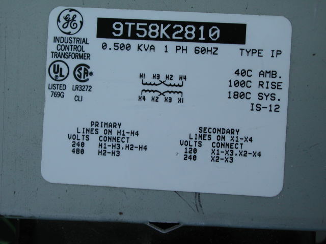
 Choice number three can be implemented using an industrial control transformer (under $100 new, way cheaper on Ebay). These transformers were originally designed for industrial machinery and used to step 480 volts down to 120 volts. They come in several power ratings. A 500 VA (.5 KVA) unit is used here. The primary and secondaries are reversed to use this as a step up transformer. I got this one on Ebay for $18. The shipping cost more than the transformer.
The voltage doubler uses two 5AR4's. I tried several types of 5AR4 tubes, Sovtek, Westinghouse, RCA, GE, International. Of these low cost brands the Sovteks gave the best regulation. These were the same tubes used in the Ongaku supply. Electrolytic capacitors are used in the power supply. An oil cap is placed in the amplifier chassis in parallel with the power supply output to insure a low output impedance at the higher frequencies.
The choke was swiped from the 300Beast. I wanted to fit this supply on the same chassis as the Ongaku supply and that choke was smaller with a lower DC resistance. Since it is not rated for 2000 volts it is placed in the ground leg of the power supply circuit.
The B+ supply is similar to the power supply used in the Simple 45 amp, except for a bigger transformer and 500 Volt rated capacitors. The transformer is a "vacuum tube" design. A 750 Volt center tapped winding (and the 5 volt winding) feed a 5AR4 with a capacitor input filter to generate + 470 volts, the same winding also feeds a pair of FREDs with a choke input filter to generate -400 volts. The 6.3 volt winding on this transformer feeds a bridge rectifier to supply the regulator on the driver board which generates the 2.5 volts for the 45's.
A separate transformer with two 12 volt 4 amp windings drive separate bridge rectifiers and capacitors to generate the two 10 volt DC supplies for the 845 filaments. I would have used a 10 volt transformer if I could find one.
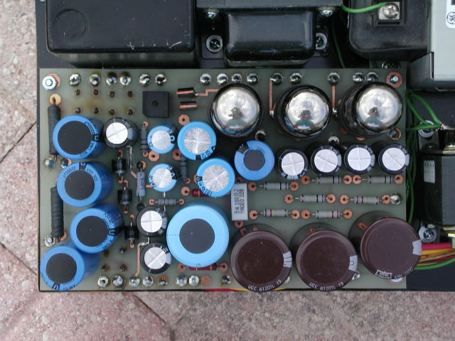
All of the components in the power supply except the iron are on a PC board. This simplifies construction and insures reliable, repeatable performance.
 The PC Board
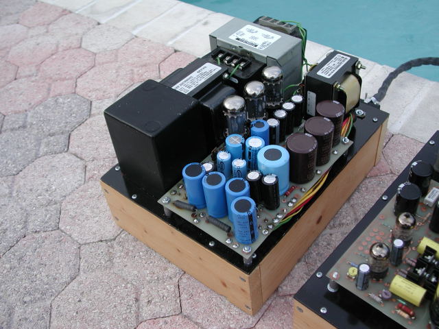
 The Completed Power Supply
Update
I had a 1500 volt 1/2 amp power supply in the house during the 833A SE amp experiments. It was from a Motorola tube type radio transmitter. Built like a tank, and weighs as much as one (about 100 pounds). I disconnected the input capacitor (which makes this a choke input supply) to lower the output voltage to about 1200 volts. Upon connecting this up to the 845SE, it became evident that I would be designing a new power supply eventually. The amplifier had much more life and the bass is better defined than ever. The crackling sound that was always present in this amp under overload conditions was gone. Some of this new life could be due to the extra 100 volts, but some was due to the regulation that was supplied by the constant voltage transformer. Unfortunately this transformer is not suitable for an audio amp due to the buzzing noise that it makes. It also weighs 75 pounds, and is about the size of the whole amp!